GR5526 (6)-Power Debug Reference for Watch Demo
[TOC]
Note: This document applies to the Reference Project ${ GR5526 _ SDK } \ projects \ peripheral \ graphics \ graphics _ lvgl _ 831 _ GPU _ demo.
1. Refer to the engineering description
Watch Demo project is a smart watch demo project based on GR5526 SK. The Lvgl 8.31 GUI framework used in the project is transplanted and optimized based on GR5526 GPU, which has the characteristics of high frame rate, good interactive effect and fast development efficiency. Users can carry out secondary development of watch or display products based on this project: add UI layout and interaction, add peripheral processing, add business interaction logic, add BLE Profile, etc. Can accelerate the user’s product cycle very well.
Because different products will be designed with different working modes, and the state transition conditions between modes are different, the design of power consumption (working) modes of products is diverse. This Watch Demo sample project provides a basic working mode management strategy. On the one hand, it provides a primary reference for users when designing working modes. On the other hand, it also helps users understand and quickly debug the low-power mode of the product.
2. Low Power Mode Background
If a chip level power evaluation of the GR5526 is required, it is recommended that ${ SDK } \ rojects \ ble \ ble _ peripheral \ ble _ app _ PCs Engineering be used. Refer to the document “GR5526 Power Consumption Mode and Power Consumption Measurement Description”. The online webpage of the document is: GR5526 Power Mode and Power Measurement Description. The background knowledge of power consumption in this document also depends on this document. Please read it first.
If you want to learn about the power consumption business logic in the OS environment, see the project ${ SDK } \ projects \ ble \ ble _ peripheral \ ble _ app _ template _ freertos. Based on GR5526, it transplants the FreeRTOS system, adapts the sleep strategy, and opens the basic BLE broadcast. It is suitable to be used as a template project for IOT products from OS to zero architecture. Online reference documents corresponding to the project
For GR5xxx series chips, the low-power sleep strategy in FreeRTOS environment is different from that in Bare (bare metal) environment. The former is designed based on the Tickless mode of FreeRTOS idle tasks, while the latter is managed in the main stack and main loop. Take care to select the appropriate engineering template depending on whether the product uses the OS.
3. Low Power Debugging Based on Watch Demo
3.1 Principle
Since the low-power consumption debugging is based on the GR5526 SK development board, it is quite different from the product environment, for example, the I/O arrangement used is different, the mounted peripherals are different, the working mode design is different, and the business logic of the Demo project is incomplete. This section mainly describes the general method of debugging. Debugging strongly related to some business scenarios, such as peripheral sleep processing method and leakage search and analysis, will not be described in detail.
3.2 Test environment setup
In this test, the current loop measurement method is used to determine the power consumption state of the system, and the voltage supply method can also be used.
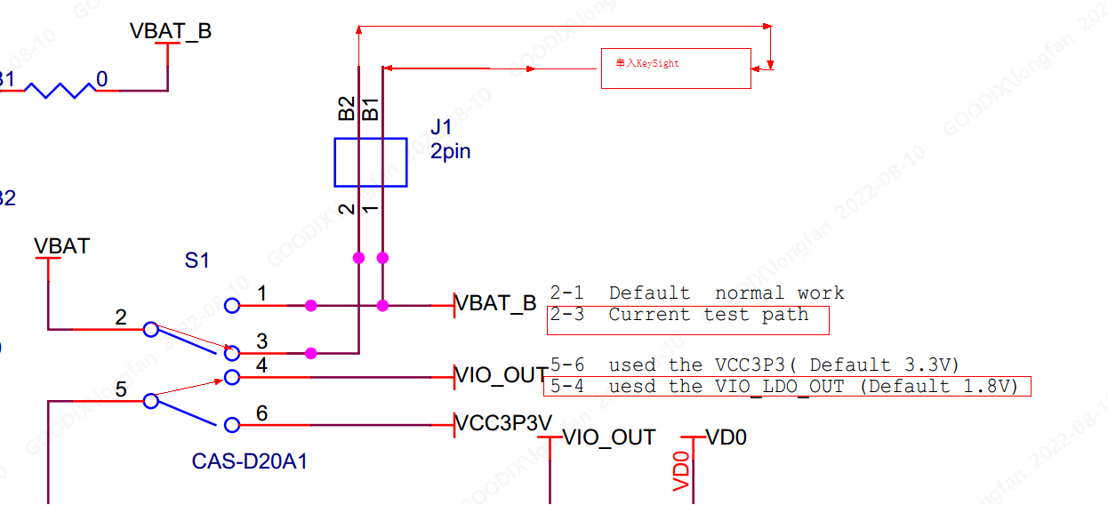
The following hardware configurations apply to the GR5526 SK Rev. B and Rev. C circuit versions. Click Reference GR5526 SK Rev. C Circuit Diagram
Key Sight is set to current measurement model
Remove the jumper cap of J1. Key Sight Output + connection J1.Pin1; Key Sight Output-Connect J1.Pin2. Connect the Key Sight to the current circuit in series
Dial switch S1 dial mode: Pin2 and Pin3 are connected, Pin4 and Pin5 are connected
Dial mode of dial switch S10: dial to VBAT side
The dial mode of dial switch S11 is: dial to VCC side
JLink-USB port is connected to PC USB for circuit power supply and Jlink debugging.
3.4 Working mode design of Watch Demo
In this reference project, three working modes of the application layer are designed:
Active bright screen working mode: all application services are in working state, GUI tasks are rendered in real time, and the screen is always bright.
Screen-off working mode: In this mode, other application services run normally, only the screen display is turned off, and GUI rendering and screen brushing are suspended for several seconds. If the system detects the behavior of touching the screen within this period of time, it will directly light up the screen and return to Active mode. If no touch activity is detected over a period of time, the system enters a screen-off sleep mode
Screen-off Sleep mode: In this mode, GUI-related tasks do not work, the screen is off, all peripherals enter the power-down or periodic execution state according to the product design, and the chip stops working and enters Sleep. The screen-off sleep mode does not prevent the execution of periodic tasks. When the periodic task is executed, the chip will wake up again and continue to enter Sleep mode after completion. In the Sleep mode of this reference project, because the Touch is stopped working (the sleep interrupt trigger wake-up is not realized, and the user needs to realize it separately according to the product needs), an additional key wake-up is added. Users can wake up the screen, power up or wake up all peripherals through SK’s K1 & K2 buttons, so that the system can re-enter the Active bright screen working mode.
In general, the currents of the above three working modes are from large to small. According to different products, the bottom current of the screen-off sleep mode should be at the level of tens to hundreds of uA (Note: the sleep current of the chip itself is only several uA, and the example values here include other power-consuming peripherals).
3.5 Sleep Mode Debugging
3.5.1 Principles
The general principles of the system sleep strategy are:
The non-idle task of the system is completed, the current work of BLE is completed, all peripherals are in the Idle state, and the distance between the next executable task and the current time is not less than 5ms. When the Idle task of FreeRTOS is entered, the chip is allowed to enter Sleep mode.
3.5.2 General conditions
The preconditions for the system to enter low-power sleep are generally:
Check if there are tasks that work all the time to ensure that the task design is in line with the product logic.
Check for periodic events less than 5ms
Ensure BLE application meets specification
Make sure that all peripherals are not working in the Idle state
In general, the first three conditions are easy to check and satisfy, and the relatively small probability is the reason why the chip cannot sleep. More probable is the last case: Some peripherals are still in working state.
3.5.3 Method for determining whether the peripheral is in working state
It is also easy to find out whether the peripheral is working or not. The SDK provides two bits of u32 variables to record whether each peripheral is working or not.
The variable itself is defined inside the SDK, and extern reference is made in the header file ${ SDK } \ drivers \ Inc \ Hal \ gr55xx _ Hal _ PWR _ mgmt. H.
The following is an enumeration of the variable name and the corresponding bit. The bit corresponding to the enumeration value indicates the current state of the corresponding peripheral: if the bit is 1, it is being used; If 0, idle mode has been entered..
When all bits of the 2 variables are 0, the condition that the peripheral is allowed to sleep is also met.
extern volatile uint32_t g_devices_state;
The number of corresponding managed peripherals is 32. The lowest bit represents whether [DMA0] works, and the highest bit represents whether [USB] works.
		typedef enum
		{
		    PERIPH_DEVICE_NUM_DMA0 = 0,
		    PERIPH_DEVICE_NUM_DMA1,     //NO.=1
		    PERIPH_DEVICE_NUM_ISO7816,  //NO.=2
		    PERIPH_DEVICE_NUM_PKC,      //NO.=3
		    PERIPH_DEVICE_NUM_QSPI0,    //NO.=4
		    PERIPH_DEVICE_NUM_QSPI1,    //NO.=5
		    PERIPH_DEVICE_NUM_QSPI2,    //NO.=6
		    PERIPH_DEVICE_NUM_SPIM,     //NO.=7
		    PERIPH_DEVICE_NUM_SPIS,     //NO.=8
		    PERIPH_DEVICE_NUM_DSPI,     //NO.=9
		    PERIPH_DEVICE_NUM_I2C0,     //NO.=10
		    PERIPH_DEVICE_NUM_I2C1,     //NO.=11
		    PERIPH_DEVICE_NUM_I2C2,     //NO.=12
		    PERIPH_DEVICE_NUM_I2C3,     //NO.=13
		    PERIPH_DEVICE_NUM_I2C4,     //NO.=14
		    PERIPH_DEVICE_NUM_I2C5,     //NO.=15
		    PERIPH_DEVICE_NUM_UART0,    //NO.=16
		    PERIPH_DEVICE_NUM_UART1,    //NO.=17
		    PERIPH_DEVICE_NUM_UART2,    //NO.=18
		    PERIPH_DEVICE_NUM_UART3,    //NO.=19
		    PERIPH_DEVICE_NUM_UART4,    //NO.=20
		    PERIPH_DEVICE_NUM_UART5,    //NO.=21
		    PERIPH_DEVICE_NUM_I2S_M,    //NO.=22
		    PERIPH_DEVICE_NUM_I2S_S,    //NO.=23
		    PERIPH_DEVICE_NUM_PDM,      //NO.=24
		    PERIPH_DEVICE_NUM_HMAC,     //NO.=25
		    PERIPH_DEVICE_NUM_RNG,      //NO.=26
		    PERIPH_DEVICE_NUM_AES,      //NO.=27
		    PERIPH_DEVICE_NUM_PWM0,     //NO.=28
		    PERIPH_DEVICE_NUM_PWM1,     //NO.=29
		    PERIPH_DEVICE_NUM_SNSADC,   //NO.=30
		    PERIPH_DEVICE_NUM_USB,      //NO.=31
		    MAX_PERIPH_DEVICE_NUM
		} periph_device_number_t;
extern volatile uint32_t g_extra_devices_state;
The corresponding managed peripherals are as follows:
		typedef enum
		{
		    EXTRA_DEVICE_NUM_CLK_CALIB = 0,
		    EXTRA_DEVICE_NUM_GPU,          //NO.=1
		    EXTRA_DEVICE_NUM_DC,           //NO.=2
		    EXTRA_DEVICE_NUM_OSPI,         //NO.=3
		    MAX_EXTRA_DEVICE_NUM
		} extra_device_number_t;
3.5.4 Examples
If the value of the G _ extra _ devices _ state variable is found to be 2 during the status check before entering the Idle to prepare for sleep, the corresponding set bit is a EXTRA _ DEVICE _ NUM _ GPU, indicating that the current GPU has not completed its work. So you can’t sleep yet.
After finding the peripheral that affects dormancy, further analyze the reason why it is still working. If it should not be working at this time, find out the reason why it is not working properly and solve it.
In case of sleep failure, the following methods can be used to view the value of the peripheral working state variable:
Using Keil’s Debug mode, the breakpoint breaks the PWR _ mgmt _ enter _ sleep _ with _ cond of the function in the port _ pm. C to view the values of two variables. This method is less efficient.
Obtain the SRAM addresses of the two variables through the Map table, and use Jlink to connect the SK board to view.
Use the Ozone debugging tool to add timed refresh monitoring to the variables. Further analyze the abnormal working peripheral by determining which bits are 1.
When the chip can periodically sleep normally, the connected JLink will be automatically disconnected due to sleep, which can also be used as an auxiliary condition to determine whether the chip enters sleep.
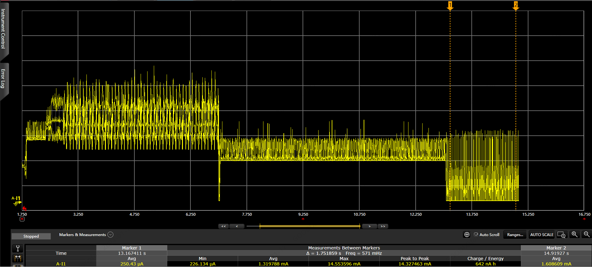
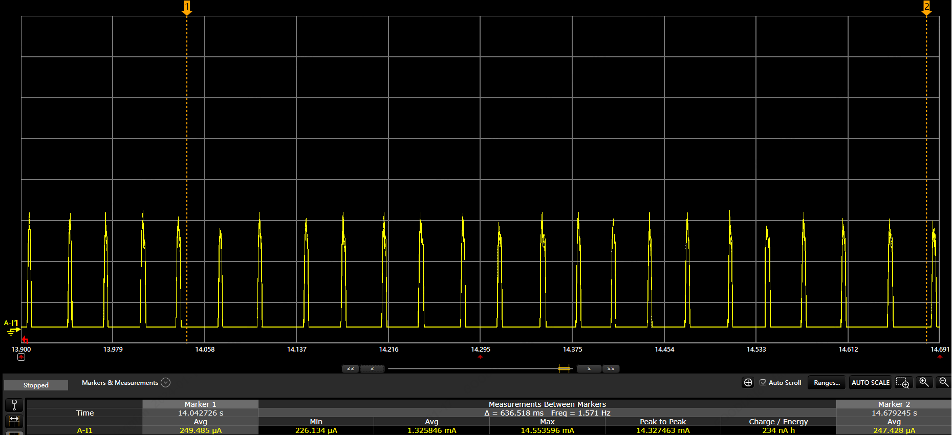
3.6 Current waveform of each operation mode
Waveform measurement uses the method of KeySight series connection into the current loop. If the voltage supply method is used, the waveform is different. The waveform mainly reflects the magnitude difference of the current of each mode, which is used to judge whether the working mode is switched normally, and does not reflect the actual current accuracy (without carefully closing the peripheral, checking the leakage and other operations related to the specific business layer).
3.6.1 Current waveform of working mode switching
Waveform 1: Current waveform change from Active modeto Screen-off modeto Sleep modeafter power-on
3.6.2 Current Waveform with BLE Broadcast Sleep
Waveform 2: current waveform expansion in sleep mode
Periodic waveform is BLE broadcast
When the system power consumption is debugged at the mode level, it can enter the detailed debugging stage, including optimizing the sleep strategy of each peripheral one by one, checking the system leakage, and improving the overall power consumption tuning of the system.