FQA for ADC
This chapter describes the problems, causes, and treatments that may occur when using the ADC module.
1. Calling the asynchronous acquisition interface keeps failing to generate a completion interrupt
Problem Description
Calling the app_adc_dma_conversion_async(conversion, TEST_CONV_LENGTH) interface to initiate an acquisition has been unable to generate a completion interrupt.
Problem Analysis
The conversion address is not 4-byte aligned. Since the internal DMA align is configured as WORD, the buffer input address is required to be 4-byte aligned.
TEST_CONV_LENGTH exceeds the DMA length limitation, here len cannot exceed 4095*2.
Conversion is a local variable, and then waits for the completion of the interrupt outside the function calling app_adc_dma_conversion_async. At this point, the original function has been exited, resulting in the release of the local variable, the target address of the DMA handling is not a legitimate address.
Handling method
Check whether the conversion is 4-byte aligned, if not, we need to force 4-byte alignment.
Check if the len parameter exceeds 4095*2.
Check if conversion is a local variable, and if it is not, we need to force it to be 4-byte aligned. Check if the input parameter len exceeds 4095*2.
Similar problem: call app_adc_multi_channel_conversion_async interface to capture, the data of the second and subsequent channels are messed up. *
2. Some of the internal reference voltage stalls are captured with large errors in the results
Problem description
When using an internal reference source, it is found that the ADC results measured by a large reference source have a large error.
Problem Analysis
The chip supply voltage is too low to support the reference voltage required for the selected reference voltage bracket. Different reference voltages require the chip supply voltage as follows:
| Reference source gear | Chip supply voltage range |
|---|---|
| 0P8V | 2.1 V to 3.8 V |
| 1P2V | 2.6 V~3.8 V |
| 1P6V | 3.2 V to 3.8 V |
Treatment
Increase the power supply voltage of the chip, or lower the reference voltage gear so that the chip power supply voltage matches the reference voltage.
3. High sampling rate with large error in the result.
Problem Description
Based on the 16 MHz ADC sampling clock, the acquired result has a big fluctuation and the error is very big.
Problem Analysis
The large impedance outside the circuit causes the charging time to be too long and more than 2 Clocks failed to establish a stable signal hold.The ADC acquisition circuit is as follows:
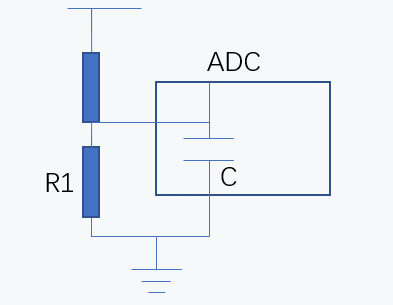
The ADC has an internal capacitance of 2 pF, which requires that the impedance R of the user’s external circuit and the ADC’s internal capacitance C form an RC charging circuit on which the charging time must not exceed the signal sampling hold time. Signal hold time is 2 ADC Clock, so the higher the configured sampling clock, the shorter the required hold time.
Processing methods
Reduce the ADC Sampling Clock frequency, or reduce the impedance R of the external circuit.
4. Slow Asynchronous Acquisition Interface
Problem Description
The app_adc_dma_conversion_async() interface is called to acquire data of the specified length, and the acquisition time is found to be relatively long, far exceeding the configured sampling speed.
Problem Analysis
It is possible that printing was added inside the callback function for sampling completion.
The asynchronous interface needs to respond to the DMA transfer completion interrupt, which will be slower than the synchronous interface.
Treatment
If you are looking for sampling speed, or to test the sampling rate, it is recommended to use the synchronous interface.
5. Synchronous capture interface fails to generate data
Problem Description
Calling app_adc_conversion_sync() to synchronize the interface acquisition, and found that it could not generate ADC data and timed out.
Problem Analysis
The acquisition interface is called in an interrupt with a higher priority than the Bluetooth LE interrupt, which conflicts with the ADC operation in PMU Calibration.
After PMU Calibration Disable ADC, it is preempted, and then in App conversion, the acquisition interface will not re-enable ADC, but only Enable ADC Clock.
Handling method
Decrease the priority of the acquisition thread, can’t call the acquisition interface at a higher priority than the Bluetooth LE interrupt; otherwise, need to coordinate the mutual exclusion relationship with the ADC operation in PMU Calibration.