OSPI PSRAM Application Notes
Note: The OSPI PSRAM is an extension of the GR5526 SoC series, available in the GR5526VGBIP and GR5526RGNIP packages. Other chip series do not include OSPI PSRAM.
1. PSRAM Address Space Layout and Management
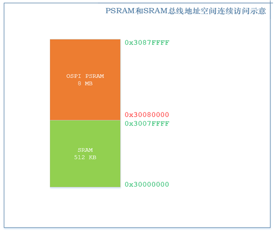
In the GR5526 SoC, one bus address space mapping range of the 512 KB SRAM is [0x30000000, 0x3007FFFF], while the bus address space mapping range of the 64Mbit OSPI PSRAM is [0x30080000, 0x3087FFFF]. They can be addressed continuously on the bus.
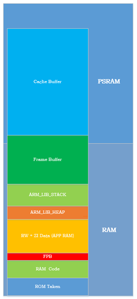
In practical application design, the SRAM area is primarily occupied by RAM Code, RW+ZI, system stack, application layer logic, and algorithms. Generally, the 512 KB SRAM will not be fully occupied, and the remaining SRAM and PSRAM together form a large heap area. Users can use it for display storage or data storage. The typical internal distribution structure is as follows:
To facilitate the management of the above internal layout in application projects, use a dedicated scatter layout file in the application project of the PSRAM version SoC (Keil version: ${SDK}\platform\soc\linker\keil\flash_scatter_graphics.sct).
To facilitate the management of the large data space composed of the remaining SRAM and PSRAM, the SDK provides dedicated heap management drivers app_graphics_mem.c and app_graphics_mem.h.
The heap management files are located at ${SDK}\components\libraries\app_graphics_mem. After registering and initializing the base address and size of the data area, you can use app_graphics_mem_malloc and app_graphics_mem_free to allocate and free data blocks.
The heap nodes and data blocks of this heap management driver are implemented separately. The heap nodes are always stored in the SRAM area, enabling data retention during sleep.
2. Initialization and Usage of PSRAM
The initialization of PSRAM is straightforward; simply call the following code. This interface will initialize both the OSPI module and the PSRAM device into operational status.
app_graphics_ospi_params_t params = PSRAM_INIT_PARAMS_Default; app_graphics_ospi_init(¶ms);
Ensure that the scatter loading file referenced by the compiler is: ${SDK}\platform\soc\linker\keil\flash_scatter_graphics.sct.
Call the following code to register the remaining SRAM and PSRAM area with the Heap manager.
mem_pwr_mgmt_mode_set(MEM_POWER_FULL_MODE);
app_graphics_mem_init((void*)GFX_MEM_BASE, GFX_MEM_SIZE);
Subsequently, it is possible to use this heap area through the app_graphics_mem_malloc and app_graphics_mem_free interfaces.
3. PSRAM Working Mode
The OSPI PSRAM is designed with two operating modes: Active and Deep-Sleep.
Active mode: In Active mode, the PSRAM is always accessible, and data is retained. During access, power consumption ranges from approximately 2 mA to 5 mA, depending on access intensity. In standby mode under Active, power consumption is about 66 μA at 20℃.
Deep-Sleep mode: When the system is in sleep mode and data retention is not required, the PSRAM can be set to Deep-Sleep mode. In Deep-Sleep mode, the PSRAM is powered down, with an operating current close to 0 μA. The PSRAM driver provides an interface for switching operating modes, allowing users to switch modes according to application needs. Currently, the supported modes are Active and Deep-Sleep.
4. PSRAM Sleep Strategy
Due to the design of the system sleep framework, there are some differences in the sleep strategies of PSRAM devices in bare-metal environments and OS environments.
In bare-metal mode, system sleep is managed by the user.
In OS mode, exemplified by FreeRTOS, the system sleep strategy is designed within the OS porting layer. These differences result in variations in PSRAM usage between the two environments.
4.1 Hibernation Strategy in Bare Metal Environment
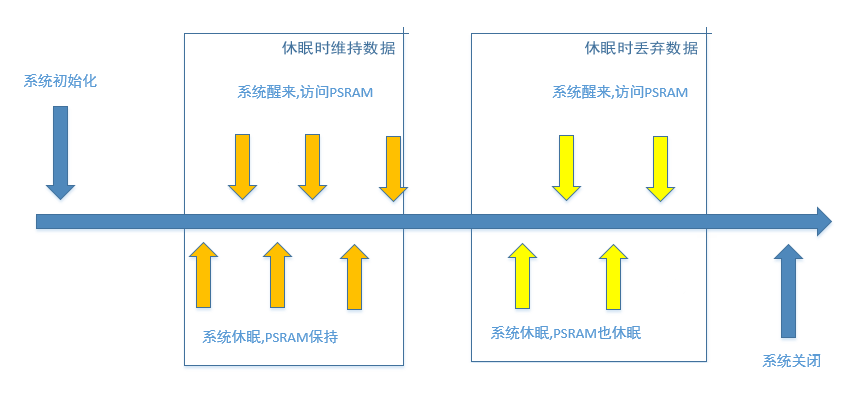
When the system initializes, it initializes the OSPI PSRAM.
If the PSRAM will not be used shortly after initialization, you can call the interface to set the PSRAM to Deep-Sleep.
Before the system goes to sleep, it will call the module’s configuration save interface to save the module’s register configuration to the Retention SRAM. However, the driver does not provide a register retention interface for the OSPI module.
During system sleep, since there is no register retention interface provided for the OSPI module, the OSPI module configuration will be lost.
When the system wakes up, it will call the module’s configuration restore interface to restore the configuration saved to the Retention SRAM before sleep back to the registers. Since the driver lacks a register restore interface, the OSPI configuration interface is used to reconfigure the OSPI (the actual measured time is a few μs, which is acceptable). From this, it can be seen that in a bare-metal environment, the system sleep strategy integrates the management of the OSPI module but does not integrate the management of the PSRAM state. This is because the PSRAM has high power consumption, and the sleep/wake time is relatively long, requiring a design closely related to the application layer’s business logic. For the application layer:
Call the initialization interface during system initialization.
When the PSRAM can be powered down for sleep, call app_graphics_ospi_set_power_state(OSPI_STATE_DEEP_SLEEP) to put the PSRAM into sleep mode.
When the PSRAM needs to work again, call app_graphics_ospi_set_power_state(OSPI_STATE_ACTIVE) to restore the PSRAM state.
If the PSRAM needs to retain data at a certain stage, after setting it to Active, do not call the sleep interface. However, this will result in additional power consumption during this period.
4.2 Sleep Strategy in RTOS Environment
Refer to the FreeRTOS project for integrated PSRAM state management within the OS.