DFU Application Introduction
1. GR5xx DFU Introduction
For detailed introduction of GR5xx DFU program, please refer to “GR5xx Firmware Upgrade Development Guide”.
GR5xx DFU program support:
Background dual-zone upgrade mode: Bank0 stores the running firmware; Bank1 caches the upgrade firmware. Application firmware running receives upgrade firmware cache at the same time, and finally overwrites the application firmware upgrade.
Non-background single-zone upgrade mode: Bank0 stores running firmware; jump from application firmware to App Bootloader firmware, receive upgrade firmware directly stored in Bank0, overwrite application firmware upgrade.
** Ordinary Mode:** Each packet of data contains a checksum field, which can be used to check the data and ACK cell phone to continue to send the next packet of data, with errors detected in time and at a slower rate.
Fast Mode: Each packet of data does not contain a parity field, the cell phone does not need to ACK to send the remaining data continuously, one-time checksum after the completion of sending, there are errors can be found in the end, the rate is faster (the upper limit depends on the efficiency of Flash data writing).
BLE and serial port communication methods.
Encryption, countersign security upgrade.
Low-cost integration of third-party cell phone apps.
Low-cost adaptation of third-party upgrade program.
This paper focuses on BLE communication about DFU function construction, precautions and problem analysis during GR5xx product development.
2. DFU Program Selection
Is it necessary to receive firmware upgrade silently in the background while the product is running, so as to save the overall time consuming for users to wait for firmware upgrade? If you need to choose the background dual-zone upgrade mode, you can only jump to the App Bootloader when overlaying the upgrade and wait for the cache to upgrade the firmware to be carried, but you need to additionally divide the same Size Bank to cache the upgraded firmware.
Whether you need to minimize Flash usage. If the Flash resources are not enough to allocate an additional same size bank to cache the upgrade firmware, choose the non-background single zone upgrade mode, jump to App Bootloader when starting to receive the upgrade firmware, wait for the upgrade firmware to be received and overwritten, and the waiting time is longer.
Whether fast upgrade is required. If the upgraded firmware is larger, or the upgrade dial such a larger Size of resources, you can choose the fast upgrade mode, although you can not abort the upgrade in time checksum, but the probability of this is smaller. Relatively speaking, the overall use of the upgrade time-consuming short.
Convention.
In order to facilitate the alignment of information, single-area non-background upgrade is called to become a small upgrade, dual-area background upgrade convention known as ** copy upgrade**.
3. Flash Layout Division
3.1 Upgrade Mode
Once the DFU scheme is confirmed (here mainly confirming the backend dual-zone upgrade mode or non-backend single-zone upgrade mode), the corresponding Flash Layout must be divided:
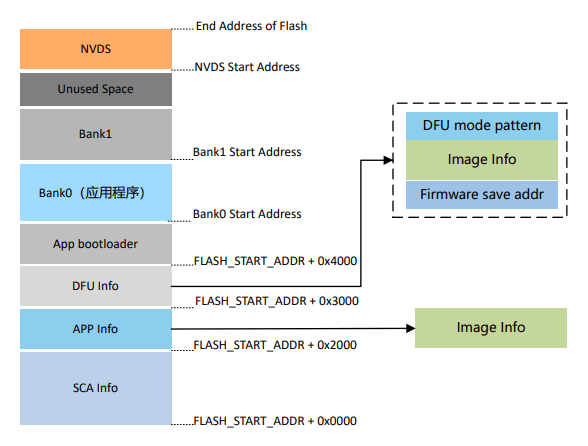
Background dual-zone upgrade mode (copy upgrade)
**Non-Background Single Zone Upgrade Mode (Small to Large)
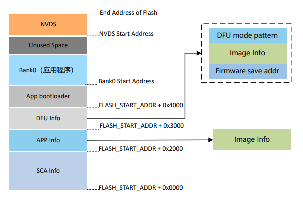
Demarcation Area Description SCA Info: SCA (System Configuration Area)
SCA Info: SCA (System Configuration Area) System Configuration Area, mainly used for storing system information and App bootloader boot parameter configuration information.
APP Info: Application Firmware Info Area, used to store the parameter information of application firmware running in Bank0 area.
**DFU Info: ** DFU firmware info area, used to store information related to new firmware in Bank1 area.
**Firmware save addr: ** Start address of new firmware save.
Image Info: Parameter information of the new firmware.
DFU mode pattern: Used to identify the current running DFU mode.
**App bootloader: ** App bootloader firmware storage and running area.
**Bank0: ** App firmware storage and running area.
**Bank1: ** New firmware cache area, new firmware that passes the validity check will be copied to Bank0.
**NVDS (Non-volatile Data Storage): ** Non-volatile data storage area.
3.2 App Bootloader Description
No matter what upgrade scheme is used, it is necessary to burn the App Bootloader to complete the firmware jump and upgrade, the rough process is as follows:
After the system is powered on, the App Bootloader starts up, verifies the DFU Info area data, and determines whether the firmware upgrade process is required and how to perform the firmware upgrade.
Verify the App Info area data, determine whether there is an instruction to jump to the application firmware, and verify whether the application firmware is valid.
Jump to the application firmware to run its logic.
3.3 Introduction to Important Details
Upgrade firmware architecture requirements
Each compiler (e.g. Keil, IAR, GCC) will not include the current firmware Image Info at the end of the compiled mutual firmware.
For DFU, it is necessary to use Image Info to verify the firmware, as well as to update Image Info to the DFU Info area.
Therefore, the compiled firmware can not be upgraded directly by GRToolbox, it will not be recognized as valid firmware, you need to use GProgrammer to convert the compiled firmware to DFU-ready firmware with Image Info (the converted firmware will add “_fw” suffix to the original firmware filename, the converted firmware will have “_fw” suffix to the original firmware filename, the converted firmware will have “_fw” suffix to the original firmware filename). (The converted firmware will add “_fw” suffix to the original firmware file name, and the converted firmware will not be converted again).
App Bootloader Jump Selection
For some production line processes, multiple firmware may need to be burned, such as App Bootloader, Application, Production Test, and DTM firmware. Refer to the App Bootloader configuration file for how to handle when the App Bootloader jumps to the specified firmware. Use the Comments in Image Info of each firmware to compare and confirm whether it is the specified firmware, and then verify the jump.
App Info area data generation
No matter using GProgrammer or PLT Config tool to burn the firmware, it will only burn the firmware Image Info to the SCA area, and the App Bootloader firmware will automatically update the valid data in the App Info area:
The App Bootloader will read the data in the App Info area at startup to verify the validity of the specified firmware.
At the first run, the App Info area data is invalid, App Bootloader will traverse the Image Info of each firmware in the SCA area according to the specified Comments, and verify it, and update the valid Info to the App Info area for the next jump.
For subsequent upgrades, App Bootloader will update the upgraded firmware Image Info in DFU Info to App Info area for next jump after the upgrade is completed.
3.4 Third Party DFU Adaptation
The third-party DFU program mentioned here usually refers to the Copy Upgrade program.The Application firmware receives the upgrade firmware from the other end is its own program, such as BLE Service, communication protocol, and the detailed logic of receiving, caching and verifying the firmware.
According to the following method, you can realize the third-party DFU video on the GR5xx platform:
DFU area Flash Layout division.
Flash API adaptation, such as erase, read and write.
Get Image Info of GR5xx upgraded firmware, and update it to DFU Info area together with DFU Info information (using
dfu_info_updateAPI).App Bootloader Cropping Retention Copy Upgrade is sufficient.
Instructions :
If the third-party DFU solution needs to package the firmware, it needs to package the firmware with Image Info. At the end of the upgrade transfer, how to get Image Info can be handled according to its own results, the following figure is an application scenario.
For the firmware with Image Info, the user needs to add the signature and other information in its own security authentication program, and the length of the additional information is not fixed.
Simply use the sliding parse method, traverse from the last position of the received firmware file to determine the GR5xx Pattern, and then based on whether the firmware check sum passes to ultimately determine whether it is the location of the Image Info information.
Update the obtained Image Info and DFU related information together to DFU Info area, (here burned directly, did not use
dfu_info_updateAPI).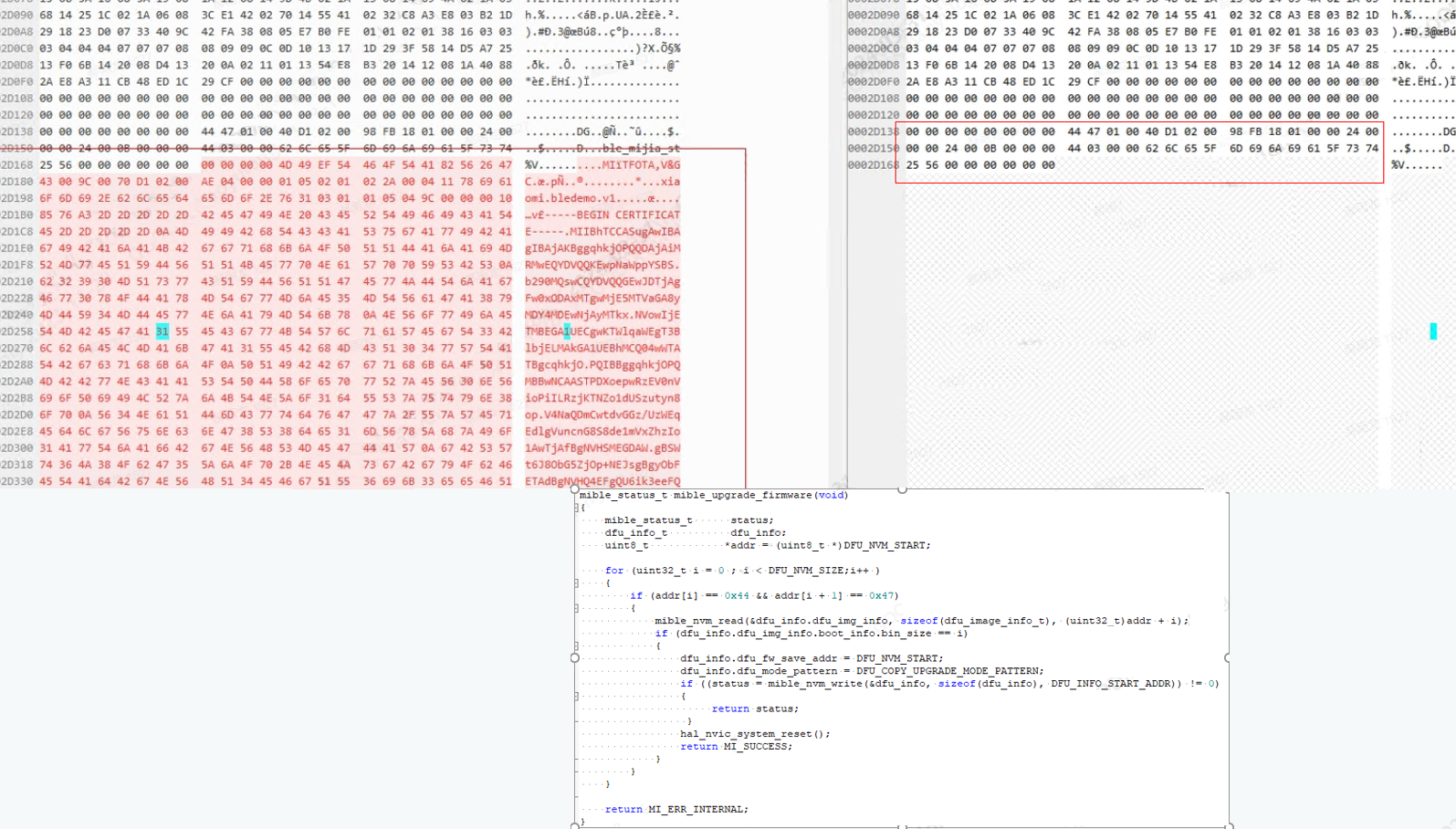
Please make sure to use the App Bootloader provided by GR5xx platform instead of implementing it by yourself, because it integrates platform-specific jump logics, such as sleep hotboot, Platform environment configuration and so on.
4. FAQ
4.1 How to enable Fast DFU mode?
Due to the evolution of GR5xx SDK, there are incompatibility issues. We have optimized GR551x SDK V2.0.1, GR5526 SDK V1.0.1, GR5525 SDK V0.8.0, GR5625 SDK V0.9.0, GR533x SDK V0.9.0, so you don’t need to do any special processing on the device side, just enable it in the function menu at the upper right corner of GRToolbox App DFU application interface. menu of GRToolbox App DFU application interface. Before this SDK version, you need to use Fast DFU components and services, please refer to the Fast DFU demo in the SDK package, and GRToolbox also needs to use Fast DFU app.
4.2 Where is the Fast DFU rate limitation and how much rate can be reached?
The Fast DFU rate limit mainly comes from the processing of data received by the device: Flash storage, after GR5xx receives the data, it caches the ring buffer and then carries and stores it to Flash. Increasing the Flash writing rate and setting the appropriate ring buffer size can increase the Fast DFU rate. It has been tested to reach 70 kbps by utilizing on-chip Flash.
Note:
In order to ensure whether to use Fast DFU case, the DFU component occupies the smallest RAM Size, so the ring Buffer size configured in the DFU component is not the optimal rate size, if you need to use Fast DFU and do not consider the RAM occupancy size, to ensure the rate of the case, you can dfu_port.c in the
DFU_BUFFER_ SIZEin dfu_port.c to 8 KB.
4.3 How is DFU low-power under RTOS?
Under RTOS, a separate task needs to be created for the DFU and dfu_schedule needs to be called. Since the probability of the DFU being used in a product is low, the task should not be kept running all the time, but should be kept pending and resumed only when an upgrade is needed. A common way to handle this is to control the hanging and resuming of the DFU task by utilizing semaphores that signal whether or not to perform an upgrade. The dfu_service_init can be utilized to register the callback of dfu enter, and when the peer needs to initiate the DFU process, the command of dfu enter will be initiated at the first time.
In addition, for the configuration of the DFU task stack size, it should be noted that: only on GR551x platform, due to the existence of a local variable buffer of 4 KB size in the ROM implementation, the DFU task needs to be configured with at least a stack size of 6 KB in order to ensure the safety of the DFU stack. This issue has been fixed for other platforms.